Friction factor and pipe roughness (fluids.friction)
This module contains correlations for single-phase friction factor in a range of geometries. It also contains several tables of reported material roughnesses, and some basic functionality showing how to calculate single-phase pressure drop.
For reporting bugs, adding feature requests, or submitting pull requests, please use the GitHub issue tracker or contact the author at Caleb.Andrew.Bell@gmail.com.
Friction Factor Interfaces
- fluids.friction.friction_factor(Re, eD=0.0, Method='Clamond', Darcy=True)[source]
Calculates friction factor. Uses a specified method, or automatically picks one from the dictionary of available methods. 29 approximations are available as well as the direct solution, described in the table below. The default is to use the exact solution.
For Re < 2040, [1] the laminar solution is always returned, regardless of selected method.
- Parameters
- Returns
- f
float Friction factor, [-]
- f
- Other Parameters
Notes
A table of the supposed limits of each correlation is as follows. Note that the spaces in the method names are placed by underscores in the actual function names and when provided as the Method argument. The default method is likely to be sufficient.
Nice name
Re min
Re max
Min
Max
Clamond
0
None
0
None
Rao Kumar 2007
None
None
None
None
Eck 1973
None
None
None
None
Jain 1976
5000
1.0E+7
4.0E-5
0.05
Avci Karagoz 2009
None
None
None
None
Swamee Jain 1976
5000
1.0E+8
1.0E-6
0.05
Churchill 1977
None
None
None
None
Brkic 2011 1
None
None
None
None
Chen 1979
4000
4.0E+8
1.0E-7
0.05
Round 1980
4000
4.0E+8
0
0.05
Papaevangelo 2010
10000
1.0E+7
1.0E-5
0.001
Fang 2011
3000
1.0E+8
0
0.05
Shacham 1980
4000
4.0E+8
None
None
Barr 1981
None
None
None
None
Churchill 1973
None
None
None
None
Moody
4000
1.0E+8
0
1
Zigrang Sylvester 1
4000
1.0E+8
4.0E-5
0.05
Zigrang Sylvester 2
4000
1.0E+8
4.0E-5
0.05
Buzzelli 2008
None
None
None
None
Haaland
4000
1.0E+8
1.0E-6
0.05
Serghides 1
None
None
None
None
Serghides 2
None
None
None
None
Tsal 1989
4000
1.0E+8
0
0.05
Alshul 1952
None
None
None
None
Wood 1966
4000
5.0E+7
1.0E-5
0.04
Manadilli 1997
5245
1.0E+8
0
0.05
Brkic 2011 2
None
None
None
None
Romeo 2002
3000
1.5E+8
0
0.05
Sonnad Goudar 2006
4000
1.0E+8
1.0E-6
0.05
References
- 1
Avila, Kerstin, David Moxey, Alberto de Lozar, Marc Avila, Dwight Barkley, and Björn Hof. “The Onset of Turbulence in Pipe Flow.” Science 333, no. 6039 (July 8, 2011): 192-96. doi:10.1126/science.1203223.
Examples
>>> friction_factor(Re=1E5, eD=1E-4)
0.01851386607747165
>>> friction_factor(Re=2.9E5, eD=1E-5, Method='Serghides_2')
0.0146199041093456
- fluids.friction.friction_factor_methods(Re, eD=0.0, check_ranges=True)[source]
Returns a list of correlation names for calculating friction factor for internal pipe flow.
- Parameters
- Returns
- methods
list List of methods which claim to be valid for the range of Re and eD given, [-]
- methods
Examples
>>> len(friction_factor_methods(Re=1E5, eD=1E-4))
30
- fluids.friction.friction_factor_curved(Re, Di, Dc, roughness=0.0, Method=None, Rec_method='Schmidt', laminar_method='Schmidt laminar', turbulent_method='Schmidt turbulent', Darcy=True)[source]
Calculates friction factor fluid flowing in a curved pipe or helical coil, supporting both laminar and turbulent regimes. Selects the appropriate regime by default, and has default correlation choices. Optionally, a specific correlation can be specified with the Method keyword.
The default correlations are those recommended in [1], and are believed to be the best publicly available.
- Parameters
- Returns
- f
float Friction factor, [-]
- f
- Other Parameters
- Method
str,optional A string of the function name to use, overriding the default turbulent/ laminar selection.
- Rec_method
str,optional Critical Reynolds number transition criteria; one of [‘Seth Stahel’, ‘Ito’, ‘Kubair Kuloor’, ‘Kutateladze Borishanskii’, ‘Schmidt’, ‘Srinivasan’]; the default is ‘Schmidt’.
- laminar_method
str,optional Friction factor correlation for the laminar regime; one of [‘White’, ‘Mori Nakayama laminar’, ‘Schmidt laminar’]; the default is ‘Schmidt laminar’.
- turbulent_method
str,optional Friction factor correlation for the turbulent regime; one of [‘Guo’, ‘Ju’, ‘Schmidt turbulent’, ‘Prasad’, ‘Mandel Nigam’, ‘Mori Nakayama turbulent’, ‘Czop’]; the default is ‘Schmidt turbulent’.
- Darcybool,
optional If False, will return fanning friction factor, 1/4 of the Darcy value
- Method
See also
fluids.geometry.HelicalCoilhelical_turbulent_fd_Schmidthelical_turbulent_fd_Srinivasanhelical_turbulent_fd_Mandal_Nigamhelical_turbulent_fd_Juhelical_turbulent_fd_Guohelical_turbulent_fd_Czophelical_turbulent_fd_Prasadhelical_turbulent_fd_Mori_Nakayamahelical_laminar_fd_Schmidthelical_laminar_fd_Mori_Nakayamahelical_laminar_fd_Whitehelical_transition_Re_Schmidthelical_transition_Re_Srinivasanhelical_transition_Re_Kutateladze_Borishanskiihelical_transition_Re_Kubair_Kuloorhelical_transition_Re_Itohelical_transition_Re_Seth_Stahel
Notes
The range of accuracy of these correlations is much than that in a straight pipe.
References
- 1
Schlunder, Ernst U, and International Center for Heat and Mass Transfer. Heat Exchanger Design Handbook. Washington: Hemisphere Pub. Corp., 1983.
Examples
>>> friction_factor_curved(Re=1E5, Di=0.02, Dc=0.5)
0.022961996738387523
- fluids.friction.friction_factor_curved_methods(Re, Di, Dc, roughness=0.0, check_ranges=True)[source]
Returns a list of correlation names for calculating friction factor of fluid flowing in a curved pipe or helical coil, supporting both laminar and turbulent regimes.
- Parameters
- Re
float Reynolds number with D=Di, [-]
- Di
float Inner diameter of the tube making up the coil, [m]
- Dc
float Diameter of the helix/coil measured from the center of the tube on one side to the center of the tube on the other side, [m]
- roughness
float,optional Roughness of pipe wall [m]
- check_rangesbool,
optional Whether or not to return only correlations suitable for the provided data, [-]
- Re
- Returns
- methods
list List of methods in the regime the specified Re is in at the given Di and Dc.
- methods
Examples
>>> friction_factor_curved_methods(Re=1E5, Di=0.02, Dc=0.5)[0]
'Schmidt turbulent'
- fluids.friction.helical_Re_crit(Di, Dc, Method='Schmidt')[source]
Calculates the transition Reynolds number for fluid flowing in a curved pipe or helical coil. Selects the appropriate regime by default. Optionally, a specific correlation can be specified with the Method keyword.
The default correlations are those recommended in [1], and are believed to be the best publicly available.
- Parameters
- Di
float Inner diameter of the tube making up the coil, [m]
- Dc
float Diameter of the helix/coil measured from the center of the tube on one side to the center of the tube on the other side, [m]
- Method
str,optional Critical Reynolds number transition criteria correlation; one of [‘Seth Stahel’, ‘Ito’, ‘Kubair Kuloor’, ‘Kutateladze Borishanskii’, ‘Schmidt’, ‘Srinivasan’]; the default is ‘Schmidt’.
- Di
- Returns
- Re_crit
float Reynolds number for critical transition between laminar and turbulent flow, [-]
- Re_crit
See also
References
- 1
Schlunder, Ernst U, and International Center for Heat and Mass Transfer. Heat Exchanger Design Handbook. Washington: Hemisphere Pub. Corp., 1983.
Examples
>>> helical_Re_crit(Di=0.02, Dc=0.5)
6946.792538856203
Pipe Friction Factor Correlations
- fluids.friction.ft_Crane(D)[source]
Calculates the Crane fully turbulent Darcy friction factor for flow in commercial pipe, as used in the Crane formulas for loss coefficients in various fittings. Note that this is not generally applicable to loss due to friction in pipes, as it does not take into account the roughness of various pipe materials. But for fittings in any type of pipe, this is the friction factor to use in the Crane [1] method to get their loss coefficients.
- Parameters
- D
float Pipe inner diameter, [m]
- D
- Returns
- fd
float Darcy Crane friction factor for fully turbulent flow, [-]
- fd
Notes
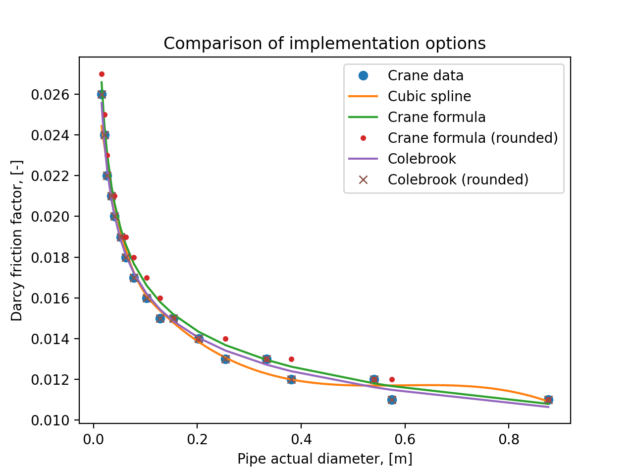
There is confusion and uncertainty regarding the friction factor table given in Crane TP 410M [1]. This function does not help: it implements a new way to obtain Crane friction factors, so that it can better be based in theory and give more precision (not accuracy) and trend better with diameters not tabulated in [1].
The data in [1] was digitized, and nominal pipe diameters were converted to actual pipe diameters. An objective function was sought which would produce the exact same values as in [1] when rounded to the same decimal place. One was found fairly easily by using the standard Colebrook friction factor formula, and using the diameter-dependent roughness values calculated with the roughness_Farshad method for bare Carbon steel. A diameter-dependent Reynolds number was required to match the values; the term is set to 7.5E6.
The formula given in [1] is:
However, this function does not match the rounded values in [1] well and it is not very clear which roughness to use. Using both the value for new commercial steel (.05 mm) or a diameter-dependent value (roughness_Farshad), values were found to be too high and too low respectively. That function is based in theory - the limit of the Colebrook equation when Re goes to infinity - but in the end real pipe flow is not infinity, and so a large error occurs from that use.
The following plot shows all these options, and that the method implemented here matches perfectly the rounded values in [1].
(
Source code,png,hires.png,pdf)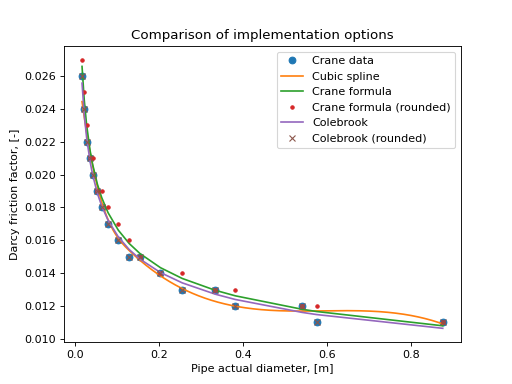
References
Examples
>>> ft_Crane(.1)
0.01628845962146481
Explicitly spelling out the function (note the exact same answer is not returned; it is accurate to 5-8 decimals however, for increased speed):
>>> Di = 0.1
>>> Colebrook(7.5E6*Di, eD=roughness_Farshad(ID='Carbon steel, bare', D=Di)/Di)
0.0162884254312
- fluids.friction.Colebrook(Re, eD, tol=None)[source]
Calculates Darcy friction factor using the Colebrook equation originally published in [1]. Normally, this function uses an exact solution to the Colebrook equation, derived with a CAS. A numerical can also be used.
- Parameters
- Re
float Reynolds number, [-]
- eD
float Relative roughness, [-]
- tol
float,optional None for analytical solution (default); user specified value to use the numerical solution; 0 to use mpmath and provide a bit-correct exact solution to the maximum fidelity of the system’s float; -1 to apply the Clamond solution where appropriate for greater speed (Re > 10), [-]
- Re
- Returns
- fd
float Darcy friction factor [-]
- fd
Notes
The solution is as follows:
Some effort to optimize this function has been made. The lambertw function from scipy is used, and is defined to solve the specific function:
This is relatively slow despite its explicit form as it uses the mathematical function lambertw which is expensive to compute.
For high relative roughness and Reynolds numbers, an OverflowError can be encountered in the solution of this equation. The numerical solution is then used.
The numerical solution provides values which are generally within an rtol of 1E-12 to the analytical solution; however, due to the different rounding order, it is possible for them to be as different as rtol 1E-5 or higher. The 1E-5 accuracy regime has been tested and confirmed numerically for hundreds of thousand of points within the region 1E-12 < Re < 1E12 and 0 < eD < 0.1.
The numerical solution attempts the secant method using scipy’s newton solver, and in the event of nonconvergence, attempts the fsolve solver as well. An initial guess is provided via the Clamond function.
The numerical and analytical solution take similar amounts of time; the mpmath solution used when tol=0 is approximately 45 times slower. This function takes approximately 8 us normally.
References
- 1
Colebrook, C F.”Turbulent Flow in Pipes, with Particular Reference to the Transition Region Between the Smooth and Rough Pipe Laws.” Journal of the ICE 11, no. 4 (February 1, 1939): 133-156. doi:10.1680/ijoti.1939.13150.
Examples
>>> Colebrook(1E5, 1E-4)
0.018513866077471
- fluids.friction.Clamond(Re, eD, fast=False)[source]
Calculates Darcy friction factor using a solution accurate to almost machine precision. Recommended very strongly. For details of the algorithm, see [1].
- Parameters
- Returns
- fd
float Darcy friction factor [-]
- fd
Notes
This is a highly optimized function, 4 times faster than the solution using the LambertW function, and faster than many other approximations which are much less accurate.
The code used here is only slightly modified than that in [1], for further performance improvements.
For 10 < Re < 1E12, and 0 < eD < 0.01, this equation has been confirmed numerically to provide a solution to the Colebrook equation accurate to an rtol of 1E-9 or better - the same level of accuracy as the analytical solution to the Colebrook equation due to floating point precision.
Comparing this to the numerical solution of the Colebrook equation, identical values are given accurate to an rtol of 1E-9 for 10 < Re < 1E100, and 0 < eD < 1 and beyond.
However, for values of Re under 10, different answers from the Colebrook equation appear and then quickly a ValueError is raised.
References
- 1(1,2)
Clamond, Didier. “Efficient Resolution of the Colebrook Equation.” Industrial & Engineering Chemistry Research 48, no. 7 (April 1, 2009): 3665-71. doi:10.1021/ie801626g. http://math.unice.fr/%7Edidierc/DidPublis/ICR_2009.pdf
Examples
>>> Clamond(1E5, 1E-4)
0.01851386607747165
- fluids.friction.friction_laminar(Re)[source]
Calculates Darcy friction factor for laminar flow, as shown in [1] or anywhere else.
Notes
For round pipes, this valid for .
Results in [2] show that this theoretical solution calculates too low of friction factors from Re = 10 and up, with an average deviation of 4%.
References
- 1
Cengel, Yunus, and John Cimbala. Fluid Mechanics: Fundamentals and Applications. Boston: McGraw Hill Higher Education, 2006.
- 2
McKEON, B. J., C. J. SWANSON, M. V. ZAGAROLA, R. J. DONNELLY, and A. J. SMITS. “Friction Factors for Smooth Pipe Flow.” Journal of Fluid Mechanics 511 (July 1, 2004): 41-44. doi:10.1017/S0022112004009796.
Examples
>>> friction_laminar(128)
0.5
- fluids.friction.Moody(Re, eD)[source]
Calculates Darcy friction factor using the method in Moody (1947) as shown in [1] and originally in [2].
- Parameters
- Returns
- fd
float Darcy friction factor [-]
- fd
Notes
Range is Re >= 4E3 and Re <= 1E8; eD >= 0 < 0.01.
References
- 1
Winning, H. and T. Coole. “Explicit Friction Factor Accuracy and Computational Efficiency for Turbulent Flow in Pipes.” Flow, Turbulence and Combustion 90, no. 1 (January 1, 2013): 1-27. doi:10.1007/s10494-012-9419-7
- 2
Moody, L.F.: An approximate formula for pipe friction factors. Trans. Am. Soc. Mech. Eng. 69,1005-1006 (1947)
Examples
>>> Moody(1E5, 1E-4)
0.01809185666808665
- fluids.friction.Blasius(Re)[source]
Calculates Darcy friction factor according to the Blasius formulation, originally presented in [1] and described more recently in [2].
Notes
Developed for 3000 < Re < 200000.
References
- 1
Blasius, H.”Das Aehnlichkeitsgesetz bei Reibungsvorgängen in Flüssigkeiten.” In Mitteilungen über Forschungsarbeiten auf dem Gebiete des Ingenieurwesens, edited by Verein deutscher Ingenieure, 1-41. Berlin, Heidelberg: Springer Berlin Heidelberg, 1913. http://rd.springer.com/chapter/10.1007/978-3-662-02239-9_1.
- 2
Hager, W. H. “Blasius: A Life in Research and Education.” In Experiments in Fluids, 566-571, 2003.
Examples
>>> Blasius(10000)
0.03164
- fluids.friction.von_Karman(eD)[source]
Calculates Darcy friction factor for rough pipes at infinite Reynolds number from the von Karman equation (as given in [1] and [2]:
Notes
This case does not actually occur; Reynolds number is always finite. It is normally applied as a “limiting” value when a pipe’s roughness is so high it has a friction factor curve effectively independent of Reynods number.
References
- 1
Rennels, Donald C., and Hobart M. Hudson. Pipe Flow: A Practical and Comprehensive Guide. 1st edition. Hoboken, N.J: Wiley, 2012.
- 2
McGovern, Jim. “Technical Note: Friction Factor Diagrams for Pipe Flow.” Paper, October 3, 2011. http://arrow.dit.ie/engschmecart/28.
Examples
>>> von_Karman(1E-4)
0.01197365149564789
- fluids.friction.Prandtl_von_Karman_Nikuradse(Re)[source]
Calculates Darcy friction factor for smooth pipes as a function of Reynolds number from the Prandtl-von Karman Nikuradse equation as given in [1] and [2]:
Notes
This equation is often stated as follows; the correct constant is not 0.8, but 2log10(2.51) or approximately 0.7993474:
This function is calculable for all Reynolds numbers between 1E151 and 1E-151. It is solved with the LambertW function from SciPy. The solution is:
References
- 1
Rennels, Donald C., and Hobart M. Hudson. Pipe Flow: A Practical and Comprehensive Guide. 1st edition. Hoboken, N.J: Wiley, 2012.
- 2
McGovern, Jim. “Technical Note: Friction Factor Diagrams for Pipe Flow.” Paper, October 3, 2011. http://arrow.dit.ie/engschmecart/28.
Examples
>>> Prandtl_von_Karman_Nikuradse(1E7)
0.008102669430
- fluids.friction.Alshul_1952(Re, eD)[source]
Calculates Darcy friction factor using the method in Alshul (1952) as shown in [1].
- Parameters
- Returns
- fd
float Darcy friction factor [-]
- fd
Notes
No range of validity specified for this equation.
References
- 1
Winning, H. and T. Coole. “Explicit Friction Factor Accuracy and Computational Efficiency for Turbulent Flow in Pipes.” Flow, Turbulence and Combustion 90, no. 1 (January 1, 2013): 1-27. doi:10.1007/s10494-012-9419-7
Examples
>>> Alshul_1952(1E5, 1E-4)
0.018382997825686878
- fluids.friction.Wood_1966(Re, eD)[source]
Calculates Darcy friction factor using the method in Wood (1966) [2] as shown in [1].
- Parameters
- Returns
- fd
float Darcy friction factor [-]
- fd
Notes
Range is 4E3 <= Re <= 5E7; 1E-5 <= eD <= 4E-2.
References
- 1
Winning, H. and T. Coole. “Explicit Friction Factor Accuracy and Computational Efficiency for Turbulent Flow in Pipes.” Flow, Turbulence and Combustion 90, no. 1 (January 1, 2013): 1-27. doi:10.1007/s10494-012-9419-7
- 2
Wood, D.J.: An Explicit Friction Factor Relationship, vol. 60. Civil Engineering American Society of Civil Engineers (1966)
Examples
>>> Wood_1966(1E5, 1E-4)
0.021587570560090762
- fluids.friction.Churchill_1973(Re, eD)[source]
Calculates Darcy friction factor using the method in Churchill (1973) [2] as shown in [1]
- Parameters
- Returns
- fd
float Darcy friction factor [-]
- fd
Notes
No range of validity specified for this equation.
References
- 1
Winning, H. and T. Coole. “Explicit Friction Factor Accuracy and Computational Efficiency for Turbulent Flow in Pipes.” Flow, Turbulence and Combustion 90, no. 1 (January 1, 2013): 1-27. doi:10.1007/s10494-012-9419-7
- 2
Churchill, Stuart W. “Empirical Expressions for the Shear Stress in Turbulent Flow in Commercial Pipe.” AIChE Journal 19, no. 2 (March 1, 1973): 375-76. doi:10.1002/aic.690190228.
Examples
>>> Churchill_1973(1E5, 1E-4)
0.01846708694482294
- fluids.friction.Eck_1973(Re, eD)[source]
Calculates Darcy friction factor using the method in Eck (1973) [2] as shown in [1].
- Parameters
- Returns
- fd
float Darcy friction factor [-]
- fd
Notes
No range of validity specified for this equation.
References
- 1
Winning, H. and T. Coole. “Explicit Friction Factor Accuracy and Computational Efficiency for Turbulent Flow in Pipes.” Flow, Turbulence and Combustion 90, no. 1 (January 1, 2013): 1-27. doi:10.1007/s10494-012-9419-7
- 2
Eck, B.: Technische Stromungslehre. Springer, New York (1973)
Examples
>>> Eck_1973(1E5, 1E-4)
0.01775666973488564
- fluids.friction.Jain_1976(Re, eD)[source]
Calculates Darcy friction factor using the method in Jain (1976) [2] as shown in [1].
- Parameters
- Returns
- fd
float Darcy friction factor [-]
- fd
Notes
Range is 5E3 <= Re <= 1E7; 4E-5 <= eD <= 5E-2.
References
- 1
Winning, H. and T. Coole. “Explicit Friction Factor Accuracy and Computational Efficiency for Turbulent Flow in Pipes.” Flow, Turbulence and Combustion 90, no. 1 (January 1, 2013): 1-27. doi:10.1007/s10494-012-9419-7
- 2
Jain, Akalank K.”Accurate Explicit Equation for Friction Factor.” Journal of the Hydraulics Division 102, no. 5 (May 1976): 674-77.
Examples
>>> Jain_1976(1E5, 1E-4)
0.018436560312693327
- fluids.friction.Swamee_Jain_1976(Re, eD)[source]
Calculates Darcy friction factor using the method in Swamee and Jain (1976) [2] as shown in [1].
- Parameters
- Returns
- fd
float Darcy friction factor [-]
- fd
Notes
Range is 5E3 <= Re <= 1E8; 1E-6 <= eD <= 5E-2.
References
- 1
Winning, H. and T. Coole. “Explicit Friction Factor Accuracy and Computational Efficiency for Turbulent Flow in Pipes.” Flow, Turbulence and Combustion 90, no. 1 (January 1, 2013): 1-27. doi:10.1007/s10494-012-9419-7
- 2
Swamee, Prabhata K., and Akalank K. Jain.”Explicit Equations for Pipe-Flow Problems.” Journal of the Hydraulics Division 102, no. 5 (May 1976): 657-664.
Examples
>>> Swamee_Jain_1976(1E5, 1E-4)
0.018452424431901808
- fluids.friction.Churchill_1977(Re, eD)[source]
Calculates Darcy friction factor using the method in Churchill and (1977) [2] as shown in [1].
- Parameters
- Returns
- fd
float Darcy friction factor [-]
- fd
Notes
No range of validity specified for this equation.
References
- 1
Winning, H. and T. Coole. “Explicit Friction Factor Accuracy and Computational Efficiency for Turbulent Flow in Pipes.” Flow, Turbulence and Combustion 90, no. 1 (January 1, 2013): 1-27. doi:10.1007/s10494-012-9419-7
- 2
Churchill, S.W.: Friction factor equation spans all fluid flow regimes. Chem. Eng. J. 91, 91-92 (1977)
Examples
>>> Churchill_1977(1E5, 1E-4)
0.018462624566280075
- fluids.friction.Chen_1979(Re, eD)[source]
Calculates Darcy friction factor using the method in Chen (1979) [2] as shown in [1].
- Parameters
- Returns
- fd
float Darcy friction factor [-]
- fd
Notes
Range is 4E3 <= Re <= 4E8; 1E-7 <= eD <= 5E-2.
References
- 1
Winning, H. and T. Coole. “Explicit Friction Factor Accuracy and Computational Efficiency for Turbulent Flow in Pipes.” Flow, Turbulence and Combustion 90, no. 1 (January 1, 2013): 1-27. doi:10.1007/s10494-012-9419-7
- 2
Chen, Ning Hsing. “An Explicit Equation for Friction Factor in Pipe.” Industrial & Engineering Chemistry Fundamentals 18, no. 3 (August 1, 1979): 296-97. doi:10.1021/i160071a019.
Examples
>>> Chen_1979(1E5, 1E-4)
0.018552817507472126
- fluids.friction.Round_1980(Re, eD)[source]
Calculates Darcy friction factor using the method in Round (1980) [2] as shown in [1].
- Parameters
- Returns
- fd
float Darcy friction factor [-]
- fd
Notes
Range is 4E3 <= Re <= 4E8; 0 <= eD <= 5E-2.
References
- 1
Winning, H. and T. Coole. “Explicit Friction Factor Accuracy and Computational Efficiency for Turbulent Flow in Pipes.” Flow, Turbulence and Combustion 90, no. 1 (January 1, 2013): 1-27. doi:10.1007/s10494-012-9419-7
- 2
Round, G. F.”An Explicit Approximation for the Friction Factor-Reynolds Number Relation for Rough and Smooth Pipes.” The Canadian Journal of Chemical Engineering 58, no. 1 (February 1, 1980): 122-23. doi:10.1002/cjce.5450580119.
Examples
>>> Round_1980(1E5, 1E-4)
0.01831475391244354
- fluids.friction.Shacham_1980(Re, eD)[source]
Calculates Darcy friction factor using the method in Shacham (1980) [2] as shown in [1].
- Parameters
- Returns
- fd
float Darcy friction factor [-]
- fd
Notes
Range is 4E3 <= Re <= 4E8
References
- 1
Winning, H. and T. Coole. “Explicit Friction Factor Accuracy and Computational Efficiency for Turbulent Flow in Pipes.” Flow, Turbulence and Combustion 90, no. 1 (January 1, 2013): 1-27. doi:10.1007/s10494-012-9419-7
- 2
Shacham, M. “Comments on: ‘An Explicit Equation for Friction Factor in Pipe.’” Industrial & Engineering Chemistry Fundamentals 19, no. 2 (May 1, 1980): 228-228. doi:10.1021/i160074a019.
Examples
>>> Shacham_1980(1E5, 1E-4)
0.01860641215097828
- fluids.friction.Barr_1981(Re, eD)[source]
Calculates Darcy friction factor using the method in Barr (1981) [2] as shown in [1].
- Parameters
- Returns
- fd
float Darcy friction factor [-]
- fd
Notes
No range of validity specified for this equation.
References
- 1
Winning, H. and T. Coole. “Explicit Friction Factor Accuracy and Computational Efficiency for Turbulent Flow in Pipes.” Flow, Turbulence and Combustion 90, no. 1 (January 1, 2013): 1-27. doi:10.1007/s10494-012-9419-7
- 2
Barr, Dih, and Colebrook White.”Technical Note. Solutions Of The Colebrook-White Function For Resistance To Uniform Turbulent Flow.” ICE Proceedings 71, no. 2 (January 6, 1981): 529-35. doi:10.1680/iicep.1981.1895.
Examples
>>> Barr_1981(1E5, 1E-4)
0.01849836032779929
- fluids.friction.Zigrang_Sylvester_1(Re, eD)[source]
- Calculates Darcy friction factor using the method in
- Parameters
- Returns
- fd
float Darcy friction factor [-]
- fd
Notes
Range is 4E3 <= Re <= 1E8; 4E-5 <= eD <= 5E-2.
References
- 1
Winning, H. and T. Coole. “Explicit Friction Factor Accuracy and Computational Efficiency for Turbulent Flow in Pipes.” Flow, Turbulence and Combustion 90, no. 1 (January 1, 2013): 1-27. doi:10.1007/s10494-012-9419-7
- 2
Zigrang, D. J., and N. D. Sylvester.”Explicit Approximations to the Solution of Colebrook’s Friction Factor Equation.” AIChE Journal 28, no. 3 (May 1, 1982): 514-15. doi:10.1002/aic.690280323.
Examples
>>> Zigrang_Sylvester_1(1E5, 1E-4)
0.018646892425980794
- fluids.friction.Zigrang_Sylvester_2(Re, eD)[source]
- Calculates Darcy friction factor using the second method in
- Parameters
- Returns
- fd
float Darcy friction factor [-]
- fd
Notes
Range is 4E3 <= Re <= 1E8; 4E-5 <= eD <= 5E-2
References
- 1
Winning, H. and T. Coole. “Explicit Friction Factor Accuracy and Computational Efficiency for Turbulent Flow in Pipes.” Flow, Turbulence and Combustion 90, no. 1 (January 1, 2013): 1-27. doi:10.1007/s10494-012-9419-7
- 2
Zigrang, D. J., and N. D. Sylvester.”Explicit Approximations to the Solution of Colebrook’s Friction Factor Equation.” AIChE Journal 28, no. 3 (May 1, 1982): 514-15. doi:10.1002/aic.690280323.
Examples
>>> Zigrang_Sylvester_2(1E5, 1E-4)
0.01850021312358548
- fluids.friction.Haaland(Re, eD)[source]
-
- Parameters
- Returns
- fd
float Darcy friction factor [-]
- fd
Notes
Range is 4E3 <= Re <= 1E8; 1E-6 <= eD <= 5E-2
References
- 1
Winning, H. and T. Coole. “Explicit Friction Factor Accuracy and Computational Efficiency for Turbulent Flow in Pipes.” Flow, Turbulence and Combustion 90, no. 1 (January 1, 2013): 1-27. doi:10.1007/s10494-012-9419-7
- 2
Haaland, S. E.”Simple and Explicit Formulas for the Friction Factor in Turbulent Pipe Flow.” Journal of Fluids Engineering 105, no. 1 (March 1, 1983): 89-90. doi:10.1115/1.3240948.
Examples
>>> Haaland(1E5, 1E-4)
0.018265053014793857
- fluids.friction.Serghides_1(Re, eD)[source]
Calculates Darcy friction factor using the method in Serghides (1984) [2] as shown in [1].
- Parameters
- Returns
- fd
float Darcy friction factor [-]
- fd
Notes
No range of validity specified for this equation.
References
- 1
Winning, H. and T. Coole. “Explicit Friction Factor Accuracy and Computational Efficiency for Turbulent Flow in Pipes.” Flow, Turbulence and Combustion 90, no. 1 (January 1, 2013): 1-27. doi:10.1007/s10494-012-9419-7
- 2
Serghides T.K (1984).”Estimate friction factor accurately” Chemical Engineering, Vol. 91(5), pp. 63-64.
Examples
>>> Serghides_1(1E5, 1E-4)
0.01851358983180063
- fluids.friction.Serghides_2(Re, eD)[source]
Calculates Darcy friction factor using the method in Serghides (1984) [2] as shown in [1].
- Parameters
- Returns
- fd
float Darcy friction factor [-]
- fd
Notes
No range of validity specified for this equation.
References
- 1
Winning, H. and T. Coole. “Explicit Friction Factor Accuracy and Computational Efficiency for Turbulent Flow in Pipes.” Flow, Turbulence and Combustion 90, no. 1 (January 1, 2013): 1-27. doi:10.1007/s10494-012-9419-7
- 2
Serghides T.K (1984).”Estimate friction factor accurately” Chemical Engineering, Vol. 91(5), pp. 63-64.
Examples
>>> Serghides_2(1E5, 1E-4)
0.018486377560664482
- fluids.friction.Tsal_1989(Re, eD)[source]
Calculates Darcy friction factor using the method in Tsal (1989) [2] as shown in [1].
if then fd = A;
if then .
- Parameters
- Returns
- fd
float Darcy friction factor [-]
- fd
Notes
Range is 4E3 <= Re <= 1E8; 0 <= eD <= 5E-2
References
- 1
Winning, H. and T. Coole. “Explicit Friction Factor Accuracy and Computational Efficiency for Turbulent Flow in Pipes.” Flow, Turbulence and Combustion 90, no. 1 (January 1, 2013): 1-27. doi:10.1007/s10494-012-9419-7
- 2
Tsal, R.J.: Altshul-Tsal friction factor equation. Heat-Piping-Air Cond. 8, 30-45 (1989)
Examples
>>> Tsal_1989(1E5, 1E-4)
0.018382997825686878
- fluids.friction.Manadilli_1997(Re, eD)[source]
Calculates Darcy friction factor using the method in Manadilli (1997) [2] as shown in [1].
- Parameters
- Returns
- fd
float Darcy friction factor [-]
- fd
Notes
Range is 5.245E3 <= Re <= 1E8; 0 <= eD <= 5E-2
References
- 1
Winning, H. and T. Coole. “Explicit Friction Factor Accuracy and Computational Efficiency for Turbulent Flow in Pipes.” Flow, Turbulence and Combustion 90, no. 1 (January 1, 2013): 1-27. doi:10.1007/s10494-012-9419-7
- 2
Manadilli, G.: Replace implicit equations with signomial functions. Chem. Eng. 104, 129 (1997)
Examples
>>> Manadilli_1997(1E5, 1E-4)
0.01856964649724108
- fluids.friction.Romeo_2002(Re, eD)[source]
Calculates Darcy friction factor using the method in Romeo (2002) [2] as shown in [1].
- Parameters
- Returns
- fd
float Darcy friction factor [-]
- fd
Notes
Range is 3E3 <= Re <= 1.5E8; 0 <= eD <= 5E-2
References
- 1
Winning, H. and T. Coole. “Explicit Friction Factor Accuracy and Computational Efficiency for Turbulent Flow in Pipes.” Flow, Turbulence and Combustion 90, no. 1 (January 1, 2013): 1-27. doi:10.1007/s10494-012-9419-7
- 2
Romeo, Eva, Carlos Royo, and Antonio Monzon.”Improved Explicit Equations for Estimation of the Friction Factor in Rough and Smooth Pipes.” Chemical Engineering Journal 86, no. 3 (April 28, 2002): 369-74. doi:10.1016/S1385-8947(01)00254-6.
Examples
>>> Romeo_2002(1E5, 1E-4)
0.018530291219676177
- fluids.friction.Sonnad_Goudar_2006(Re, eD)[source]
Calculates Darcy friction factor using the method in Sonnad and Goudar (2006) [2] as shown in [1].
- Parameters
- Returns
- fd
float Darcy friction factor [-]
- fd
Notes
Range is 4E3 <= Re <= 1E8; 1E-6 <= eD <= 5E-2
References
- 1
Winning, H. and T. Coole. “Explicit Friction Factor Accuracy and Computational Efficiency for Turbulent Flow in Pipes.” Flow, Turbulence and Combustion 90, no. 1 (January 1, 2013): 1-27. doi:10.1007/s10494-012-9419-7
- 2
Travis, Quentin B., and Larry W. Mays.”Relationship between Hazen-William and Colebrook-White Roughness Values.” Journal of Hydraulic Engineering 133, no. 11 (November 2007): 1270-73. doi:10.1061/(ASCE)0733-9429(2007)133:11(1270).
Examples
>>> Sonnad_Goudar_2006(1E5, 1E-4)
0.0185971269898162
- fluids.friction.Rao_Kumar_2007(Re, eD)[source]
Calculates Darcy friction factor using the method in Rao and Kumar (2007) [2] as shown in [1].
- Parameters
- Returns
- fd
float Darcy friction factor [-]
- fd
Notes
No range of validity specified for this equation. This equation is fit to original experimental friction factor data. Accordingly, this equation should not be used unless appropriate consideration is given.
References
- 1
Winning, H. and T. Coole. “Explicit Friction Factor Accuracy and Computational Efficiency for Turbulent Flow in Pipes.” Flow, Turbulence and Combustion 90, no. 1 (January 1, 2013): 1-27. doi:10.1007/s10494-012-9419-7
- 2
Rao, A.R., Kumar, B.: Friction factor for turbulent pipe flow. Division of Mechanical Sciences, Civil Engineering Indian Institute of Science Bangalore, India ID Code 9587 (2007)
Examples
>>> Rao_Kumar_2007(1E5, 1E-4)
0.01197759334600925
- fluids.friction.Buzzelli_2008(Re, eD)[source]
Calculates Darcy friction factor using the method in Buzzelli (2008) [2] as shown in [1].
- Parameters
- Returns
- fd
float Darcy friction factor [-]
- fd
Notes
No range of validity specified for this equation.
References
- 1
Winning, H. and T. Coole. “Explicit Friction Factor Accuracy and Computational Efficiency for Turbulent Flow in Pipes.” Flow, Turbulence and Combustion 90, no. 1 (January 1, 2013): 1-27. doi:10.1007/s10494-012-9419-7
- 2
Buzzelli, D.: Calculating friction in one step. Mach. Des. 80, 54-55 (2008)
Examples
>>> Buzzelli_2008(1E5, 1E-4)
0.018513948401365277
- fluids.friction.Avci_Karagoz_2009(Re, eD)[source]
Calculates Darcy friction factor using the method in Avci and Karagoz (2009) [2] as shown in [1].
- Parameters
- Returns
- fd
float Darcy friction factor [-]
- fd
Notes
No range of validity specified for this equation.
References
- 1
Winning, H. and T. Coole. “Explicit Friction Factor Accuracy and Computational Efficiency for Turbulent Flow in Pipes.” Flow, Turbulence and Combustion 90, no. 1 (January 1, 2013): 1-27. doi:10.1007/s10494-012-9419-7
- 2
Avci, Atakan, and Irfan Karagoz.”A Novel Explicit Equation for Friction Factor in Smooth and Rough Pipes.” Journal of Fluids Engineering 131, no. 6 (2009): 061203. doi:10.1115/1.3129132.
Examples
>>> Avci_Karagoz_2009(1E5, 1E-4)
0.01857058061066499
- fluids.friction.Papaevangelo_2010(Re, eD)[source]
Calculates Darcy friction factor using the method in Papaevangelo (2010) [2] as shown in [1].
- Parameters
- Returns
- fd
float Darcy friction factor [-]
- fd
Notes
Range is 1E4 <= Re <= 1E7; 1E-5 <= eD <= 1E-3
References
- 1
Winning, H. and T. Coole. “Explicit Friction Factor Accuracy and Computational Efficiency for Turbulent Flow in Pipes.” Flow, Turbulence and Combustion 90, no. 1 (January 1, 2013): 1-27. doi:10.1007/s10494-012-9419-7
- 2
Papaevangelou, G., Evangelides, C., Tzimopoulos, C.: A New Explicit Relation for the Friction Factor Coefficient in the Darcy-Weisbach Equation, pp. 166-172. Protection and Restoration of the Environment Corfu, Greece: University of Ioannina Greece and Stevens Institute of Technology New Jersey (2010)
Examples
>>> Papaevangelo_2010(1E5, 1E-4)
0.015685600818488177
- fluids.friction.Brkic_2011_1(Re, eD)[source]
Calculates Darcy friction factor using the method in Brkic (2011) [2] as shown in [1].
- Parameters
- Returns
- fd
float Darcy friction factor [-]
- fd
Notes
No range of validity specified for this equation.
References
- 1
Winning, H. and T. Coole. “Explicit Friction Factor Accuracy and Computational Efficiency for Turbulent Flow in Pipes.” Flow, Turbulence and Combustion 90, no. 1 (January 1, 2013): 1-27. doi:10.1007/s10494-012-9419-7
- 2
Brkic, Dejan.”Review of Explicit Approximations to the Colebrook Relation for Flow Friction.” Journal of Petroleum Science and Engineering 77, no. 1 (April 2011): 34-48. doi:10.1016/j.petrol.2011.02.006.
Examples
>>> Brkic_2011_1(1E5, 1E-4)
0.01812455874141297
- fluids.friction.Brkic_2011_2(Re, eD)[source]
Calculates Darcy friction factor using the method in Brkic (2011) [2] as shown in [1].
- Parameters
- Returns
- fd
float Darcy friction factor [-]
- fd
Notes
No range of validity specified for this equation.
References
- 1
Winning, H. and T. Coole. “Explicit Friction Factor Accuracy and Computational Efficiency for Turbulent Flow in Pipes.” Flow, Turbulence and Combustion 90, no. 1 (January 1, 2013): 1-27. doi:10.1007/s10494-012-9419-7
- 2
Brkic, Dejan.”Review of Explicit Approximations to the Colebrook Relation for Flow Friction.” Journal of Petroleum Science and Engineering 77, no. 1 (April 2011): 34-48. doi:10.1016/j.petrol.2011.02.006.
Examples
>>> Brkic_2011_2(1E5, 1E-4)
0.018619745410688716
- fluids.friction.Fang_2011(Re, eD)[source]
Calculates Darcy friction factor using the method in Fang (2011) [2] as shown in [1].
- Parameters
- Returns
- fd
float Darcy friction factor [-]
- fd
Notes
Range is 3E3 <= Re <= 1E8; 0 <= eD <= 5E-2
References
- 1
Winning, H. and T. Coole. “Explicit Friction Factor Accuracy and Computational Efficiency for Turbulent Flow in Pipes.” Flow, Turbulence and Combustion 90, no. 1 (January 1, 2013): 1-27. doi:10.1007/s10494-012-9419-7
- 2
Fang, Xiande, Yu Xu, and Zhanru Zhou.”New Correlations of Single-Phase Friction Factor for Turbulent Pipe Flow and Evaluation of Existing Single-Phase Friction Factor Correlations.” Nuclear Engineering and Design, The International Conference on Structural Mechanics in Reactor Technology (SMiRT19) Special Section, 241, no. 3 (March 2011): 897-902. doi:10.1016/j.nucengdes.2010.12.019.
Examples
>>> Fang_2011(1E5, 1E-4)
0.018481390682985432
- fluids.friction.LAMINAR_TRANSITION_PIPE = 2040.0
Believed to be the most accurate result to date. Accurate to +/- 10. Avila, Kerstin, David Moxey, Alberto de Lozar, Marc Avila, Dwight Barkley, and Björn Hof. “The Onset of Turbulence in Pipe Flow.” Science 333, no. 6039 (July 8, 2011): 192-196. doi:10.1126/science.1203223.
Curved Pipe Friction Factor Correlations
- fluids.friction.helical_laminar_fd_White(Re, Di, Dc)[source]
Calculates Darcy friction factor for a fluid flowing inside a curved pipe such as a helical coil under laminar conditions, using the method of White [1] as shown in [2].
- Parameters
- Returns
- fd
float Darcy friction factor for a curved pipe [-]
- fd
Notes
The range of validity of this equation is , .
The form of the equation means it yields nonsense results for De < 11.6; at De < 11.6, the equation is modified to return the straight pipe value.
This model is recommended in [3], with a slight modification for Dean numbers larger than 2000.
References
- 1
White, C. M. “Streamline Flow through Curved Pipes.” Proceedings of the Royal Society of London A: Mathematical, Physical and Engineering Sciences 123, no. 792 (April 6, 1929): 645-63. doi:10.1098/rspa.1929.0089.
- 2
El-Genk, Mohamed S., and Timothy M. Schriener. “A Review and Correlations for Convection Heat Transfer and Pressure Losses in Toroidal and Helically Coiled Tubes.” Heat Transfer Engineering 0, no. 0 (June 7, 2016): 1-28. doi:10.1080/01457632.2016.1194693.
- 3
Blevins, Robert D. Applied Fluid Dynamics Handbook. New York, N.Y.: Van Nostrand Reinhold Co., 1984.
Examples
>>> helical_laminar_fd_White(250, .02, .1)
0.4063281817830202
- fluids.friction.helical_laminar_fd_Mori_Nakayama(Re, Di, Dc)[source]
Calculates Darcy friction factor for a fluid flowing inside a curved pipe such as a helical coil under laminar conditions, using the method of Mori and Nakayama [1] as shown in [2] and [3].
- Parameters
- Returns
- fd
float Darcy friction factor for a curved pipe [-]
- fd
Notes
The range of validity of this equation is .
The form of the equation means it yields nonsense results for De < 42.328; under that, the equation is modified to return the value at De=42.328, which is a multiplier of 1.405296 on the straight pipe friction factor.
References
- 1
Mori, Yasuo, and Wataru Nakayama. “Study on Forced Convective Heat Transfer in Curved Pipes : 1st Report, Laminar Region.” Transactions of the Japan Society of Mechanical Engineers 30, no. 216 (1964): 977-88. doi:10.1299/kikai1938.30.977.
- 2
El-Genk, Mohamed S., and Timothy M. Schriener. “A Review and Correlations for Convection Heat Transfer and Pressure Losses in Toroidal and Helically Coiled Tubes.” Heat Transfer Engineering 0, no. 0 (June 7, 2016): 1-28. doi:10.1080/01457632.2016.1194693.
- 3
Pimenta, T. A., and J. B. L. M. Campos. “Friction Losses of Newtonian and Non-Newtonian Fluids Flowing in Laminar Regime in a Helical Coil.” Experimental Thermal and Fluid Science 36 (January 2012): 194-204. doi:10.1016/j.expthermflusci.2011.09.013.
Examples
>>> helical_laminar_fd_Mori_Nakayama(250, .02, .1)
0.42224582857795434
- fluids.friction.helical_laminar_fd_Schmidt(Re, Di, Dc)[source]
Calculates Darcy friction factor for a fluid flowing inside a curved pipe such as a helical coil under laminar conditions, using the method of Schmidt [1] as shown in [2] and [3].
- Parameters
- Returns
- fd
float Darcy friction factor for a curved pipe [-]
- fd
Notes
The range of validity of this equation is specified only for Re, .
The form of the equation is such that as the curvature becomes negligible, straight tube result is obtained.
References
- 1
Schmidt, Eckehard F. “Wärmeübergang Und Druckverlust in Rohrschlangen.” Chemie Ingenieur Technik 39, no. 13 (July 10, 1967): 781-89. doi:10.1002/cite.330391302.
- 2
El-Genk, Mohamed S., and Timothy M. Schriener. “A Review and Correlations for Convection Heat Transfer and Pressure Losses in Toroidal and Helically Coiled Tubes.” Heat Transfer Engineering 0, no. 0 (June 7, 2016): 1-28. doi:10.1080/01457632.2016.1194693.
- 3
Pimenta, T. A., and J. B. L. M. Campos. “Friction Losses of Newtonian and Non-Newtonian Fluids Flowing in Laminar Regime in a Helical Coil.” Experimental Thermal and Fluid Science 36 (January 2012): 194-204. doi:10.1016/j.expthermflusci.2011.09.013.
Examples
>>> helical_laminar_fd_Schmidt(250, .02, .1)
0.47460725672835236
- fluids.friction.helical_turbulent_fd_Schmidt(Re, Di, Dc, roughness=0)[source]
Calculates Darcy friction factor for a fluid flowing inside a curved pipe such as a helical coil under turbulent conditions, using the method of Schmidt [1], also shown in [2].
For :
For :
- Parameters
- Returns
- fd
float Darcy friction factor for a curved pipe [-]
- fd
Notes
Valid from the transition to turbulent flow up to . At very low curvatures, converges on the straight pipe result.
References
- 1
Schmidt, Eckehard F. “Wärmeübergang Und Druckverlust in Rohrschlangen.” Chemie Ingenieur Technik 39, no. 13 (July 10, 1967): 781-89. doi:10.1002/cite.330391302.
- 2
El-Genk, Mohamed S., and Timothy M. Schriener. “A Review and Correlations for Convection Heat Transfer and Pressure Losses in Toroidal and Helically Coiled Tubes.” Heat Transfer Engineering 0, no. 0 (June 7, 2016): 1-28. doi:10.1080/01457632.2016.1194693.
Examples
>>> helical_turbulent_fd_Schmidt(1E4, 0.01, .02)
0.08875550767040916
- fluids.friction.helical_turbulent_fd_Mori_Nakayama(Re, Di, Dc)[source]
Calculates Darcy friction factor for a fluid flowing inside a curved pipe such as a helical coil under turbulent conditions, using the method of Mori and Nakayama [1], also shown in [2] and [3].
- Parameters
- Returns
- fd
float Darcy friction factor for a curved pipe [-]
- fd
Notes
Valid from the transition to turbulent flow up to . Does not use a straight pipe correlation, and so will not converge on the straight pipe result at very low curvature.
References
- 1
Mori, Yasuo, and Wataru Nakayama. “Study of Forced Convective Heat Transfer in Curved Pipes (2nd Report, Turbulent Region).” International Journal of Heat and Mass Transfer 10, no. 1 (January 1, 1967): 37-59. doi:10.1016/0017-9310(67)90182-2.
- 2
El-Genk, Mohamed S., and Timothy M. Schriener. “A Review and Correlations for Convection Heat Transfer and Pressure Losses in Toroidal and Helically Coiled Tubes.” Heat Transfer Engineering 0, no. 0 (June 7, 2016): 1-28. doi:10.1080/01457632.2016.1194693.
- 3
Ali, Shaukat. “Pressure Drop Correlations for Flow through Regular Helical Coil Tubes.” Fluid Dynamics Research 28, no. 4 (April 2001): 295-310. doi:10.1016/S0169-5983(00)00034-4.
Examples
>>> helical_turbulent_fd_Mori_Nakayama(1E4, 0.01, .2)
0.037311802071379796
- fluids.friction.helical_turbulent_fd_Prasad(Re, Di, Dc, roughness=0)[source]
Calculates Darcy friction factor for a fluid flowing inside a curved pipe such as a helical coil under turbulent conditions, using the method of Prasad [1], also shown in [2].
- Parameters
- Returns
- fd
float Darcy friction factor for a curved pipe [-]
- fd
Notes
No range of validity was specified, but the experiments used were with coil/tube diameter ratios of 17.24 and 34.9, hot water in the tube, and . At very low curvatures, converges on the straight pipe result.
References
- 1
Prasad, B. V. S. S. S., D. H. Das, and A. K. Prabhakar. “Pressure Drop, Heat Transfer and Performance of a Helically Coiled Tubular Exchanger.” Heat Recovery Systems and CHP 9, no. 3 (January 1, 1989): 249-56. doi:10.1016/0890-4332(89)90008-2.
- 2
El-Genk, Mohamed S., and Timothy M. Schriener. “A Review and Correlations for Convection Heat Transfer and Pressure Losses in Toroidal and Helically Coiled Tubes.” Heat Transfer Engineering 0, no. 0 (June 7, 2016): 1-28. doi:10.1080/01457632.2016.1194693.
Examples
>>> helical_turbulent_fd_Prasad(1E4, 0.01, .2)
0.043313098093994626
- fluids.friction.helical_turbulent_fd_Czop(Re, Di, Dc)[source]
Calculates Darcy friction factor for a fluid flowing inside a curved pipe such as a helical coil under turbulent conditions, using the method of Czop [1], also shown in [2].
- Parameters
- Returns
- fd
float Darcy friction factor for a curved pipe [-]
- fd
Notes
Valid for . Does not use a straight pipe correlation, and so will not converge on the straight pipe result at very low curvature.
References
- 1
Czop, V., D. Barbier, and S. Dong. “Pressure Drop, Void Fraction and Shear Stress Measurements in an Adiabatic Two-Phase Flow in a Coiled Tube.” Nuclear Engineering and Design 149, no. 1 (September 1, 1994): 323-33. doi:10.1016/0029-5493(94)90298-4.
- 2
El-Genk, Mohamed S., and Timothy M. Schriener. “A Review and Correlations for Convection Heat Transfer and Pressure Losses in Toroidal and Helically Coiled Tubes.” Heat Transfer Engineering 0, no. 0 (June 7, 2016): 1-28. doi:10.1080/01457632.2016.1194693.
Examples
>>> helical_turbulent_fd_Czop(1E4, 0.01, .2)
0.02979575250574106
- fluids.friction.helical_turbulent_fd_Guo(Re, Di, Dc)[source]
Calculates Darcy friction factor for a fluid flowing inside a curved pipe such as a helical coil under turbulent conditions, using the method of Guo [1], also shown in [2].
- Parameters
- Returns
- fd
float Darcy friction factor for a curved pipe [-]
- fd
Notes
Valid for . Does not use a straight pipe correlation, and so will not converge on the straight pipe result at very low curvature.
References
- 1
Guo, Liejin, Ziping Feng, and Xuejun Chen. “An Experimental Investigation of the Frictional Pressure Drop of Steam-water Two-Phase Flow in Helical Coils.” International Journal of Heat and Mass Transfer 44, no. 14 (July 2001): 2601-10. doi:10.1016/S0017-9310(00)00312-4.
- 2
El-Genk, Mohamed S., and Timothy M. Schriener. “A Review and Correlations for Convection Heat Transfer and Pressure Losses in Toroidal and Helically Coiled Tubes.” Heat Transfer Engineering 0, no. 0 (June 7, 2016): 1-28. doi:10.1080/01457632.2016.1194693.
Examples
>>> helical_turbulent_fd_Guo(2E5, 0.01, .2)
0.022189161013253147
- fluids.friction.helical_turbulent_fd_Ju(Re, Di, Dc, roughness=0.0)[source]
Calculates Darcy friction factor for a fluid flowing inside a curved pipe such as a helical coil under turbulent conditions, using the method of Ju et al. [1], also shown in [2].
- Parameters
- Returns
- fd
float Darcy friction factor for a curved pipe [-]
- fd
Notes
Claimed to be valid for all turbulent conditions with . At very low curvatures, converges on the straight pipe result.
References
- 1
Ju, Huaiming, Zhiyong Huang, Yuanhui Xu, Bing Duan, and Yu Yu. “Hydraulic Performance of Small Bending Radius Helical Coil-Pipe.” Journal of Nuclear Science and Technology 38, no. 10 (October 1, 2001): 826-31. doi:10.1080/18811248.2001.9715102.
- 2
El-Genk, Mohamed S., and Timothy M. Schriener. “A Review and Correlations for Convection Heat Transfer and Pressure Losses in Toroidal and Helically Coiled Tubes.” Heat Transfer Engineering 0, no. 0 (June 7, 2016): 1-28. doi:10.1080/01457632.2016.1194693.
Examples
>>> helical_turbulent_fd_Ju(1E4, 0.01, .2)
0.04945959480770937
- fluids.friction.helical_turbulent_fd_Srinivasan(Re, Di, Dc)[source]
Calculates Darcy friction factor for a fluid flowing inside a curved pipe such as a helical coil under turbulent conditions, using the method of Srinivasan [1], as shown in [2] and [3].
- Parameters
- Returns
- fd
float Darcy friction factor for a curved pipe [-]
- fd
Notes
Valid for 0.01 < Di/Dc < 0.15, with no Reynolds number criteria given in [2] or [3].
[2] recommends this method, using the transition criteria of Srinivasan as well. [3] recommends using either this method or the Ito method. This method did not make it into the popular review articles on curved flow.
References
- 1
Srinivasan, PS, SS Nandapurkar, and FA Holland. “Friction Factors for Coils.” TRANSACTIONS OF THE INSTITUTION OF CHEMICAL ENGINEERS AND THE CHEMICAL ENGINEER 48, no. 4-6 (1970): T156
- 2(1,2,3)
Blevins, Robert D. Applied Fluid Dynamics Handbook. New York, N.Y.: Van Nostrand Reinhold Co., 1984.
- 3(1,2,3)
Rohsenow, Warren and James Hartnett and Young Cho. Handbook of Heat Transfer, 3E. New York: McGraw-Hill, 1998.
Examples
>>> helical_turbulent_fd_Srinivasan(1E4, 0.01, .02)
0.0570745212117107
- fluids.friction.helical_turbulent_fd_Mandal_Nigam(Re, Di, Dc, roughness=0)[source]
Calculates Darcy friction factor for a fluid flowing inside a curved pipe such as a helical coil under turbulent conditions, using the method of Mandal and Nigam [1], also shown in [2].
- Parameters
- Returns
- fd
float Darcy friction factor for a curved pipe [-]
- fd
Notes
Claimed to be valid for all turbulent conditions with . At very low curvatures, converges on the straight pipe result.
References
- 1
Mandal, Monisha Mridha, and K. D. P. Nigam. “Experimental Study on Pressure Drop and Heat Transfer of Turbulent Flow in Tube in Tube Helical Heat Exchanger.” Industrial & Engineering Chemistry Research 48, no. 20 (October 21, 2009): 9318-24. doi:10.1021/ie9002393.
- 2
El-Genk, Mohamed S., and Timothy M. Schriener. “A Review and Correlations for Convection Heat Transfer and Pressure Losses in Toroidal and Helically Coiled Tubes.” Heat Transfer Engineering 0, no. 0 (June 7, 2016): 1-28. doi:10.1080/01457632.2016.1194693.
Examples
>>> helical_turbulent_fd_Mandal_Nigam(1E4, 0.01, .2)
0.03831658117115902
- fluids.friction.helical_transition_Re_Seth_Stahel(Di, Dc)[source]
Calculates the transition Reynolds number for flow inside a curved or helical coil between laminar and turbulent flow, using the method of [1].
- Parameters
- Returns
- Re_crit
float Transition Reynolds number between laminar and turbulent [-]
- Re_crit
Notes
At very low curvatures, converges to Re = 1900.
References
- 1
Seth, K. K., and E. P. Stahel. “HEAT TRANSFER FROM HELICAL COILS IMMERSED IN AGITATED VESSELS.” Industrial & Engineering Chemistry 61, no. 6 (June 1, 1969): 39-49. doi:10.1021/ie50714a007.
Examples
>>> helical_transition_Re_Seth_Stahel(1, 7.)
7645.0599897402535
- fluids.friction.helical_transition_Re_Ito(Di, Dc)[source]
Calculates the transition Reynolds number for flow inside a curved or helical coil between laminar and turbulent flow, using the method of [1], as shown in [2] and in [3].
- Parameters
- Returns
- Re_crit
float Transition Reynolds number between laminar and turbulent [-]
- Re_crit
Notes
At very low curvatures, converges to Re = 0. Recommended for
References
- 1
H. Ito. “Friction factors for turbulent flow in curved pipes.” Journal Basic Engineering, Transactions of the ASME, 81 (1959): 123-134.
- 2
El-Genk, Mohamed S., and Timothy M. Schriener. “A Review and Correlations for Convection Heat Transfer and Pressure Losses in Toroidal and Helically Coiled Tubes.” Heat Transfer Engineering 0, no. 0 (June 7, 2016): 1-28. doi:10.1080/01457632.2016.1194693.
- 3
Mori, Yasuo, and Wataru Nakayama. “Study on Forced Convective Heat Transfer in Curved Pipes.” International Journal of Heat and Mass Transfer 10, no. 5 (May 1, 1967): 681-95. doi:10.1016/0017-9310(67)90113-5.
Examples
>>> helical_transition_Re_Ito(1, 7.)
10729.972844697186
- fluids.friction.helical_transition_Re_Kubair_Kuloor(Di, Dc)[source]
Calculates the transition Reynolds number for flow inside a curved or helical coil between laminar and turbulent flow, using the method of [1], as shown in [2].
- Parameters
- Returns
- Re_crit
float Transition Reynolds number between laminar and turbulent [-]
- Re_crit
Notes
At very low curvatures, converges to Re = 0. Recommended for
References
- 1
Kubair, Venugopala, and N. R. Kuloor. “Heat Transfer to Newtonian Fluids in Coiled Pipes in Laminar Flow.” International Journal of Heat and Mass Transfer 9, no. 1 (January 1, 1966): 63-75. doi:10.1016/0017-9310(66)90057-3.
- 2
El-Genk, Mohamed S., and Timothy M. Schriener. “A Review and Correlations for Convection Heat Transfer and Pressure Losses in Toroidal and Helically Coiled Tubes.” Heat Transfer Engineering 0, no. 0 (June 7, 2016): 1-28. doi:10.1080/01457632.2016.1194693.
Examples
>>> helical_transition_Re_Kubair_Kuloor(1, 7.)
8625.986927588123
- fluids.friction.helical_transition_Re_Kutateladze_Borishanskii(Di, Dc)[source]
Calculates the transition Reynolds number for flow inside a curved or helical coil between laminar and turbulent flow, using the method of [1], also shown in [2].
- Parameters
- Returns
- Re_crit
float Transition Reynolds number between laminar and turbulent [-]
- Re_crit
Notes
At very low curvatures, converges to Re = 2300. Recommended for
References
- 1
Kutateladze, S. S, and V. M Borishanskiĭ. A Concise Encyclopedia of Heat Transfer. Oxford; New York: Pergamon Press, 1966.
- 2
El-Genk, Mohamed S., and Timothy M. Schriener. “A Review and Correlations for Convection Heat Transfer and Pressure Losses in Toroidal and Helically Coiled Tubes.” Heat Transfer Engineering 0, no. 0 (June 7, 2016): 1-28. doi:10.1080/01457632.2016.1194693.
Examples
>>> helical_transition_Re_Kutateladze_Borishanskii(1, 7.)
7121.143774574058
- fluids.friction.helical_transition_Re_Schmidt(Di, Dc)[source]
Calculates the transition Reynolds number for flow inside a curved or helical coil between laminar and turbulent flow, using the method of [1], also shown in [2] and [3]. Correlation recommended in [3].
- Parameters
- Returns
- Re_crit
float Transition Reynolds number between laminar and turbulent [-]
- Re_crit
Notes
At very low curvatures, converges to Re = 2300. Recommended for
References
- 1
Schmidt, Eckehard F. “Wärmeübergang Und Druckverlust in Rohrschlangen.” Chemie Ingenieur Technik 39, no. 13 (July 10, 1967): 781-89. doi:10.1002/cite.330391302.
- 2
El-Genk, Mohamed S., and Timothy M. Schriener. “A Review and Correlations for Convection Heat Transfer and Pressure Losses in Toroidal and Helically Coiled Tubes.” Heat Transfer Engineering 0, no. 0 (June 7, 2016): 1-28. doi:10.1080/01457632.2016.1194693.
- 3(1,2)
Schlunder, Ernst U, and International Center for Heat and Mass Transfer. Heat Exchanger Design Handbook. Washington: Hemisphere Pub. Corp., 1983.
Examples
>>> helical_transition_Re_Schmidt(1, 7.)
10540.094061770815
- fluids.friction.helical_transition_Re_Srinivasan(Di, Dc)[source]
Calculates the transition Reynolds number for flow inside a curved or helical coil between laminar and turbulent flow, using the method of [1], also shown in [2] and [3]. Correlation recommended in [3].
- Parameters
- Returns
- Re_crit
float Transition Reynolds number between laminar and turbulent [-]
- Re_crit
Notes
At very low curvatures, converges to Re = 2100. Recommended for .
References
- 1
Srinivasan, P. S., Nandapurkar, S. S., and Holland, F. A., “Pressure Drop and Heat Transfer in Coils”, Chemical Engineering, 218, CE131-119, (1968).
- 2
El-Genk, Mohamed S., and Timothy M. Schriener. “A Review and Correlations for Convection Heat Transfer and Pressure Losses in Toroidal and Helically Coiled Tubes.” Heat Transfer Engineering 0, no. 0 (June 7, 2016): 1-28. doi:10.1080/01457632.2016.1194693.
- 3(1,2)
Rohsenow, Warren and James Hartnett and Young Cho. Handbook of Heat Transfer, 3E. New York: McGraw-Hill, 1998.
Examples
>>> helical_transition_Re_Srinivasan(1, 7.)
11624.704719832524
Other Geometry Friction Factor Correlations
- fluids.friction.friction_plate_Martin_1999(Re, chevron_angle)[source]
Calculates Darcy friction factor for single-phase flow in a Chevron-style plate heat exchanger according to [1].
- Parameters
- Re
float Reynolds number with respect to the hydraulic diameter of the channels, [-]
- chevron_angle
float Angle of the plate corrugations with respect to the vertical axis (the direction of flow if the plates were straight), between 0 and 90. Many plate exchangers use two alternating patterns; use their average angle for that situation [degrees]
- Re
- Returns
- fd
float Darcy friction factor [-]
- fd
Notes
Based on experimental data from Re from 200 - 10000 and enhancement factors calculated with chevron angles of 0 to 80 degrees. See PlateExchanger for further clarification on the definitions.
The length the friction factor gets multiplied by is not the flow path length, but rather the straight path length from port to port as if there were no chevrons.
Note there is a discontinuity at Re = 2000 for the transition from laminar to turbulent flow, although the literature suggests the transition is actually smooth.
This was first developed in [2] and only minor modifications by the original author were made before its republication in [1]. This formula is also suggested in [3]
References
- 1(1,2)
Martin, Holger. “Economic optimization of compact heat exchangers.” EF-Conference on Compact Heat Exchangers and Enhancement Technology for the Process Industries, Banff, Canada, July 18-23, 1999, 1999. https://publikationen.bibliothek.kit.edu/1000034866.
- 2
Martin, Holger. “A Theoretical Approach to Predict the Performance of Chevron-Type Plate Heat Exchangers.” Chemical Engineering and Processing: Process Intensification 35, no. 4 (January 1, 1996): 301-10. https://doi.org/10.1016/0255-2701(95)04129-X.
- 3
Shah, Ramesh K., and Dusan P. Sekulic. Fundamentals of Heat Exchanger Design. 1st edition. Hoboken, NJ: Wiley, 2002.
Examples
>>> friction_plate_Martin_1999(Re=20000, chevron_angle=45)
0.7818916308365043
- fluids.friction.friction_plate_Martin_VDI(Re, chevron_angle)[source]
Calculates Darcy friction factor for single-phase flow in a Chevron-style plate heat exchanger according to [1].
- Parameters
- Re
float Reynolds number with respect to the hydraulic diameter of the channels, [-]
- chevron_angle
float Angle of the plate corrugations with respect to the vertical axis (the direction of flow if the plates were straight), between 0 and 90. Many plate exchangers use two alternating patterns; use their average angle for that situation [degrees]
- Re
- Returns
- fd
float Darcy friction factor [-]
- fd
See also
Notes
Based on experimental data from Re from 200 - 10000 and enhancement factors calculated with chevron angles of 0 to 80 degrees. See PlateExchanger for further clarification on the definitions.
The length the friction factor gets multiplied by is not the flow path length, but rather the straight path length from port to port as if there were no chevrons.
Note there is a discontinuity at Re = 2000 for the transition from laminar to turbulent flow, although the literature suggests the transition is actually smooth.
This is a revision of the Martin’s earlier model, adjusted to predidct higher friction factors.
There are three parameters in this model, a, b and c; it is posisble to adjust them to better fit a know exchanger’s pressure drop.
References
- 1
Gesellschaft, V. D. I., ed. VDI Heat Atlas. 2nd edition. Berlin; New York:: Springer, 2010.
Examples
>>> friction_plate_Martin_VDI(Re=20000, chevron_angle=45)
0.93076451142552
- fluids.friction.friction_plate_Kumar(Re, chevron_angle)[source]
Calculates Darcy friction factor for single-phase flow in a well-designed Chevron-style plate heat exchanger according to [1]. The data is believed to have been developed by APV International Limited, since acquired by SPX Corporation. This uses a curve fit of that data published in [2].
C2 and p are coefficients looked up in a table, with varying ranges of Re validity and chevron angle validity. See the source for their exact values.
- Parameters
- Re
float Reynolds number with respect to the hydraulic diameter of the channels, [-]
- chevron_angle
float Angle of the plate corrugations with respect to the vertical axis (the direction of flow if the plates were straight), between 0 and 90. Many plate exchangers use two alternating patterns; use their average angle for that situation [degrees]
- Re
- Returns
- fd
float Darcy friction factor [-]
- fd
Notes
Data on graph from Re=0.1 to Re=10000, with chevron angles 30 to 65 degrees. See PlateExchanger for further clarification on the definitions.
It is believed the constants used in this correlation were curve-fit to the actual graph in [1] by the author of [2] as there is no
The length the friction factor gets multiplied by is not the flow path length, but rather the straight path length from port to port as if there were no chevrons.
As the coefficients change, there are numerous small discontinuities, although the data on the graphs is continuous with sharp transitions of the slope.
The author of [1] states clearly this correlation is “applicable only to well designed Chevron PHEs”.
References
- 1(1,2,3)
Kumar, H. “The plate heat exchanger: construction and design.” In First U.K. National Conference on Heat Transfer: Held at the University of Leeds, 3-5 July 1984, Institute of Chemical Engineering Symposium Series, vol. 86, pp. 1275-1288. 1984.
- 2(1,2)
Ayub, Zahid H. “Plate Heat Exchanger Literature Survey and New Heat Transfer and Pressure Drop Correlations for Refrigerant Evaporators.” Heat Transfer Engineering 24, no. 5 (September 1, 2003): 3-16. doi:10.1080/01457630304056.
Examples
>>> friction_plate_Kumar(Re=2000, chevron_angle=30)
2.9760669055634517
- fluids.friction.friction_plate_Muley_Manglik(Re, chevron_angle, plate_enlargement_factor)[source]
Calculates Darcy friction factor for single-phase flow in a Chevron-style plate heat exchanger according to [1], also shown and recommended in [2].
- Parameters
- Re
float Reynolds number with respect to the hydraulic diameter of the channels, [-]
- chevron_angle
float Angle of the plate corrugations with respect to the vertical axis (the direction of flow if the plates were straight), between 0 and 90. Many plate exchangers use two alternating patterns; use their average angle for that situation [degrees]
- plate_enlargement_factor
float The extra surface area multiplier as compared to a flat plate caused the corrugations, [-]
- Re
- Returns
- fd
float Darcy friction factor [-]
- fd
Notes
Based on experimental data of plate enacement factors up to 1.5, and valid for Re > 1000 and chevron angles from 30 to 60 degrees with sinusoidal shape. See PlateExchanger for further clarification on the definitions.
The length the friction factor gets multiplied by is not the flow path length, but rather the straight path length from port to port as if there were no chevrons.
This is a continuous model with no discontinuities.
References
- 1
Muley, A., and R. M. Manglik. “Experimental Study of Turbulent Flow Heat Transfer and Pressure Drop in a Plate Heat Exchanger With Chevron Plates.” Journal of Heat Transfer 121, no. 1 (February 1, 1999): 110-17. doi:10.1115/1.2825923.
- 2
Ayub, Zahid H. “Plate Heat Exchanger Literature Survey and New Heat Transfer and Pressure Drop Correlations for Refrigerant Evaporators.” Heat Transfer Engineering 24, no. 5 (September 1, 2003): 3-16. doi:10.1080/01457630304056.
Examples
>>> friction_plate_Muley_Manglik(Re=2000, chevron_angle=45, plate_enlargement_factor=1.2)
1.0880870804075413
Experimental Friction Data
- fluids.friction.oregon_smooth_data = ([11.21, 20.22, 29.28, 43.19, 57.73, 64.58, 86.05, 113.3, 135.3, 157.5, 179.4, 206.4, 228.0, 270.9, 315.2, 358.9, 402.9, 450.2, 522.5, 583.1, 671.8, 789.8, 891.0, 1013.0, 1197.0, 1300.0, 1390.0, 1669.0, 1994.0, 2227.0, 2554.0, 2868.0, 2903.0, 2926.0, 2955.0, 2991.0, 2997.0, 3047.0, 3080.0, 3264.0, 3980.0, 4835.0, 5959.0, 8162.0, 10900.0, 13650.0, 18990.0, 29430.0, 40850.0, 59220.0, 84760.0, 120000.0, 176000.0, 237700.0, 298200.0, 467800.0, 587500.0, 824200.0, 1050000.0], [5.537, 3.492, 2.329, 1.523, 1.173, 0.9863, 0.7826, 0.5709, 0.4815, 0.4182, 0.3655, 0.3237, 0.2884, 0.2433, 0.2077, 0.1834, 0.1656, 0.1475, 0.1245, 0.1126, 0.09917, 0.08501, 0.07722, 0.06707, 0.0588, 0.05328, 0.04815, 0.04304, 0.03739, 0.03405, 0.03091, 0.02804, 0.03182, 0.03846, 0.03363, 0.04124, 0.035, 0.03875, 0.04285, 0.0426, 0.03995, 0.03797, 0.0361, 0.03364, 0.03088, 0.02903, 0.0267, 0.02386, 0.02086, 0.02, 0.01805, 0.01686, 0.01594, 0.01511, 0.01462, 0.01365, 0.01313, 0.01244, 0.01198])
Holds a tuple of experimental results from the smooth pipe flow experiments presented in McKEON, B. J., C. J. SWANSON, M. V. ZAGAROLA, R. J. DONNELLY, and A. J. SMITS. “Friction Factors for Smooth Pipe Flow.” Journal of Fluid Mechanics 511 (July 1, 2004): 41-44. doi:10.1017/S0022112004009796.
Roughness
- fluids.friction.material_roughness(ID, D=None, optimism=None)[source]
Searches through either a dict of clean pipe materials or used pipe materials and conditions and returns the ID of the nearest material. Search is performed with either the standard library’s difflib or with the thefuzz module if available.
- Parameters
- ID
str Search terms for matching pipe materials, [-]
- D
float,optional Diameter of desired pipe; used only if ID is in [2], [m]
- optimismbool,
optional For values in [1], a minimum, maximum, and average value is normally given; if True, returns the minimum roughness; if False, the maximum roughness; and if None, returns the average roughness. Most entries do not have all three values, so fallback logic to return the closest entry is used, [-]
- ID
- Returns
- roughness
float Retrieved or calculated roughness, [m]
- roughness
References
- 1
Idel`chik, I. E, and A. S Ginevskiĭ. Handbook of Hydraulic Resistance. Redding, CT: Begell House, 2007.
- 2
Farshad, Fred F., and Herman H. Rieke. “Surface Roughness Design Values for Modern Pipes.” SPE Drilling & Completion 21, no. 3 (September 1, 2006): 212-215. doi:10.2118/89040-PA.
Examples
>>> material_roughness('condensate pipes')
0.0005
- fluids.friction.nearest_material_roughness(name, clean=None)[source]
Searches through either a dict of clean pipe materials or used pipe materials and conditions and returns the ID of the nearest material. Search is performed with either the standard library’s difflib or with the thefuzz module if available.
- Parameters
- Returns
- ID
str String for lookup of roughness of a pipe, in either roughness_clean_names or HHR_roughness depending on if clean is True, [-]
- ID
References
- 1
Idel`chik, I. E, and A. S Ginevskiĭ. Handbook of Hydraulic Resistance. Redding, CT: Begell House, 2007.
Examples
>>> nearest_material_roughness('condensate pipes', clean=False)
'Seamless steel tubes, Condensate pipes in open systems or periodically operated steam pipelines'
- fluids.friction.roughness_Farshad(ID=None, D=None, coeffs=None)[source]
Calculates of retrieves the roughness of a pipe based on the work of [1]. This function will return an average value for pipes of a given material, or if diameter is provided, will calculate one specifically for the pipe inner diameter according to the following expression with constants A and B:
Please not that A has units of inches, and B requires D to be in inches as well.
The list of supported materials is as follows:
‘Plastic coated’
‘Carbon steel, honed bare’
‘Cr13, electropolished bare’
‘Cement lining’
‘Carbon steel, bare’
‘Fiberglass lining’
‘Cr13, bare’
If coeffs and D are given, the custom coefficients for the equation as given by the user will be used and ID is not required.
- Parameters
- ID
str,optional Name of pipe material from above list
- D
float,optional Actual inner diameter of pipe, [m]
- coeffs
tuple,optional (A, B) Coefficients to use directly, instead of looking them up; they are actually dimensional, in the forms (inch^-B, -) but only coefficients with those dimensions are available [-]
- ID
- Returns
- epsilon
float Roughness of pipe [m]
- epsilon
Notes
The diameter-dependent form provides lower roughness values for larger diameters.
The measurements were based on DIN 4768/1 (1987), using both a “Dektak ST Surface Profiler” and a “Hommel Tester T1000”. Both instruments were found to be in agreement. A series of flow tests, in which pressure drop directly measured, were performed as well, with nitrogen gas as an operating fluid. The accuracy of the data from these tests is claimed to be within 1%.
Using those results, the authors back-calculated what relative roughness values would be necessary to produce the observed pressure drops. The average difference between this back-calculated roughness and the measured roughness was 6.75%.
For microchannels, this model will predict roughness much larger than the actual channel diameter.
References
- 1
Farshad, Fred F., and Herman H. Rieke. “Surface Roughness Design Values for Modern Pipes.” SPE Drilling & Completion 21, no. 3 (September 1, 2006): 212-215. doi:10.2118/89040-PA.
Examples
>>> roughness_Farshad('Cr13, bare', 0.05)
5.3141677781137006e-05
- fluids.friction.HHR_roughness = {'Asbestos cement tubes, Average': (0.0006, None, None), 'Asbestos cement tubes, New': (5e-05, 0.0001, None), 'Cast-iron tubes, Cleaned after extensive use': (0.0003, 0.0015, None), 'Cast-iron tubes, Coated with asphalt': (0.00012, 0.0003, None), 'Cast-iron tubes, Deposits visible': (0.001, 0.0015, None), 'Cast-iron tubes, New, bituminized': (0.0001, 0.00015, None), 'Cast-iron tubes, Severely corroded': (None, 0.003, None), 'Cast-iron tubes, Substantial deposits': (0.002, 0.004, None), 'Cast-iron tubes, Used and corroded': (0.001, 0.0015, None), 'Cast-iron tubes, Used water pipelines': (None, None, 0.0014), 'Cement tubes, Joints, non smoothed': (0.0019, 0.0064, None), 'Cement tubes, Non processed': (0.001, 0.002, None), 'Cement tubes, Smoothed': (0.0003, 0.0008, None), 'Cement-mortar plaster channels, Plaster, cement, smoothed joints and protrusions, and a casing': (5e-05, 0.00022, None), 'Cement-mortar plaster channels, Steel trowled': (None, None, 0.0005), 'Concrete water conduits, no finish, Brushed air-placed, either sprayed concrete or concrete on more concrete': (None, None, 0.0023), 'Concrete water conduits, no finish, Conduits for water, sprayed surface of concrete': (0.0005, 0.001, None), 'Concrete water conduits, no finish, Hand-smoothed cement finish and smoothed joints': (0.00015, 0.00035, None), 'Concrete water conduits, no finish, New and finished with plater; excellent manufacture (joints aligned, prime coated and smoothed)': (5e-05, 0.00015, None), 'Concrete water conduits, no finish, New, very well manufactured, hand smoothed, prime-coated joints': (0.0001, 0.0002, None), 'Concrete water conduits, no finish, Non-smoothed air-placed, either sprayed concrete or concrete on more concrete': (0.003, 0.006, None), 'Concrete water conduits, no finish, Old, poor fitting and manufacture; with an overgrown surface and deposits of sand and gravel': (0.001, 0.004, None), 'Concrete water conduits, no finish, Smoothed air-placed, either sprayed concrete or concrete on more concrete': (0.006, 0.017, 0.0005), 'Concrete water conduits, no finish, Used and corroded; with a wavy surface and wood framework': (0.001, 0.004, None), 'Concrete water conduits, no finish, Used, no deposits, moderately smooth, steel or wooden casing, joints prime coated but not smoothed': (0.0003, 0.0006, None), 'Concrete water conduits, no finish, Used, prefabricated monoliths, cement plaster (wood floated), rough joints': (0.0005, 0.001, None), 'Concrete water conduits, no finish, Very old; damaged surface, very overgrown': (0.005, None, None), 'Concrete water conduits, no finish, Water conduit, finished with smoothed plaster': (0.005, None, None), 'Galzanized sheet steel, New': (None, None, 0.00015), 'Galzanized sheet steel, Used previously for water': (None, None, 0.00018), 'Galzanized steel tubes, Bright galvanization; new': (7e-05, 0.0001, None), 'Galzanized steel tubes, Ordinary galvanization': (0.0001, 0.00015, None), 'Glass tubes, Glass': (1.5e-06, 1e-05, None), 'Other, Plaster over a screen': (0.01, 0.015, None), 'Other, Salt-glazed ceramic': (None, None, 0.0014), 'Other, Slag and alabaster-filling': (0.001, 0.0015, None), 'Other, Slag-concrete': (None, None, 0.0015), 'Plywood tubes, Birch plywood, longitudal grain, good quality': (3e-05, 5e-05, None), 'Plywood tubes, Birch plywood, transverse grain, good quality': (None, None, 0.00012), 'Reinforced concrete tubes, New': (0.00025, 0.00034, None), 'Reinforced concrete tubes, Nonprocessed': (0.0025, None, None), 'Riveted steel tubes, Extremely poor surface; overlapping and uneven joints': (0.005, None, None), 'Riveted steel tubes, Riveted laterally and longitudinally with one line; lacquered on the inside': (0.0003, 0.0004, None), 'Riveted steel tubes, Riveted laterally and longitudinally with two lines; with or without lacquer on the inside and without corrosion': (0.0006, 0.0007, None), 'Riveted steel tubes, Riveted laterally with four line and longitudinally with six lines; overlapping joints inside': (None, None, 0.004), 'Riveted steel tubes, Riveted laterally with one line and longitudinally with two lines; thickly lacquered or torred on the inside': (0.0012, 0.0014, None), 'Riveted steel tubes, Riveted longitudinally with six lines, after extensive use': (None, None, 0.002), 'Roofing steel sheets, Not Oiled': (2e-05, 4e-05, None), 'Roofing steel sheets, Oiled': (0.00015, 0.0011, None), 'Rough channels in rock, Blast-hewed, little jointing': (0.1, 0.14, None), 'Rough channels in rock, Blast-hewed, substantial jointing': (0.13, 0.5, None), 'Rough channels in rock, Roughly cut or very uneven surface': (0.5, 1.5, None), 'Seamless steel tubes, Bituminized': (None, 4e-05, None), 'Seamless steel tubes, Casings in gas wells, different conditions, several years of use': (6e-05, 0.00022, None), 'Seamless steel tubes, Cleaned, following years of use': (None, 4e-05, None), 'Seamless steel tubes, Compressed air piping': (None, None, 0.0008), 'Seamless steel tubes, Condensate pipes in open systems or periodically operated steam pipelines': (None, None, 0.0005), 'Seamless steel tubes, Corroded, moderately ': (None, None, 0.0004), 'Seamless steel tubes, Following multiple year as a gas pipeline': (4e-05, 0.0002, None), 'Seamless steel tubes, Following multiple years of operation, generally corroded or with small amounts of scale': (0.00015, 0.001, None), 'Seamless steel tubes, Following one year as a gas pipeline': (None, None, 0.00012), 'Seamless steel tubes, Heating systems piping; either superheated steam pipes, or just water pipes of systems with deaerators and chemical treatment': (None, None, 0.0001), 'Seamless steel tubes, Heating systems, saturated steam ducts or water pipes (with minor water leakage < 0.5%, and balance water deaerated)': (None, None, 0.0002), 'Seamless steel tubes, New and unused': (2e-05, 0.0001, None), 'Seamless steel tubes, Oil pipelines, intermediate operating conditions ': (None, None, 0.0002), 'Seamless steel tubes, Poor condition': (0.005, None, None), 'Seamless steel tubes, Scale, small depositions only ': (None, None, 0.0004), 'Seamless steel tubes, Used water piping': (0.0012, 0.0015, None), 'Seamless steel tubes, Water heating piping without deaeration but with chemical treatment of water; leakage up to 3%; or condensate piping operated periodically': (None, None, 0.001), 'Seamless steel tubes, Water heating system pipelines, any source': (None, None, 0.0002), 'Seamless tubes made from brass, copper, lead, aluminum, Commercially smooth': (1.5e-06, 1e-05, None), 'Steel tubes, Glass enamel coat': (1e-06, 1e-05, None), 'Steel tubes, New': (0.00025, 0.001, None), 'Steel water conduits in generating stations, New, clean, coated, bituminized when manufactured': (1.4e-05, 1.8e-05, None), 'Steel water conduits in generating stations, New, clean, coated, bituminized when manufactured, with transverse welded joints': (0.0002, 0.0006, None), 'Steel water conduits in generating stations, New, clean, coated, bituminized, curved': (0.0001, 0.0014, None), 'Steel water conduits in generating stations, New, clean, coated, galvanized': (0.0001, 0.0002, None), 'Steel water conduits in generating stations, New, clean, coated, roughly galvanized': (0.0004, 0.0007, None), 'Steel water conduits in generating stations, New, clean, seamless (without joints), well fitted': (1.5e-05, 4e-05, None), 'Steel water conduits in generating stations, New, clean, welded lengthwise and well fitted': (1.2e-05, 3e-05, None), 'Steel water conduits in generating stations, New, clean, welded lengthwise and well fitted, with transverse welded joints': (8e-05, 0.00017, None), 'Steel water conduits in generating stations, Used, clean, moderate corrosion or slight deposits': (0.0003, 0.0007, None), 'Steel water conduits in generating stations, Used, clean, previously cleaned of either deposits or rust': (0.00015, 0.0002, None), 'Steel water conduits in generating stations, Used, clean, severe corrosion': (0.0008, 0.0015, None), 'Steel water conduits in generating stations, Used, clean, slight corrosion': (0.0001, 0.0003, None), 'Unlined tunnels, Rocks, gneiss, diameter 3-13.5 m': (0.3, 0.7, None), 'Unlined tunnels, Rocks, granite, diameter 3-9 m': (0.2, 0.7, None), 'Unlined tunnels, Shale, diameter, diameter 9-12 m': (0.25, 0.65, None), 'Unlined tunnels, Shale, nephrite bearing, diameter 3-8 m': (None, None, 0.2), 'Unlined tunnels, Shale, quartz, quartzile, diameter 7-10 m': (0.2, 0.6, None), 'Unlined tunnels, Shale, sedimentary, diameter 4-7 m': (None, None, 0.4), 'Used steel water conduits in generating stations, Used, all welded, <2 years use, no deposits': (0.00012, 0.00024, None), 'Used steel water conduits in generating stations, Used, all welded, <20 years use, no deposits': (0.0006, 0.005, None), 'Used steel water conduits in generating stations, Used, heavy corrosion, or with incrustation (deposit 1.5 - 9 mm deep)': (0.003, 0.005, None), 'Used steel water conduits in generating stations, Used, heavy corrosion, or with incrustation (deposit 3 - 25 mm deep)': (0.006, 0.0065, None), 'Used steel water conduits in generating stations, Used, inside coating, bituminized, < 2 years use': (0.0001, 0.00035, None), 'Used steel water conduits in generating stations, Used, iron-bacterial corrosion': (0.003, 0.004, None), 'Welded steel tubes, Appreciable deposits': (0.002, 0.004, None), 'Welded steel tubes, Double or simple transverse riveted joints; with or without lacquer; without corrosion': (0.0006, 0.0007, None), 'Welded steel tubes, Gas mains, many years of use, deposits of resin/naphthalene': (None, None, 0.0024), 'Welded steel tubes, Gas mains, many years of use, with layered deposits': (None, None, 0.0011), 'Welded steel tubes, Good condition': (4e-05, 0.0001, None), 'Welded steel tubes, Heavily corroded and with double transverse riveted joints': (None, None, 0.002), 'Welded steel tubes, Lacquered inside but rusted': (0.00095, 0.001, None), 'Welded steel tubes, New and covered with bitumen': (None, None, 5e-05), 'Welded steel tubes, Non-corroded and with double transverse riveted joints': (0.0012, 0.0015, None), 'Welded steel tubes, Poor condition': (0.005, None, None), 'Welded steel tubes, Small deposits': (None, None, 0.0015), 'Welded steel tubes, Surface looks like new, 10 mm lacquer inside, even joints': (0.0003, 0.0004, None), 'Welded steel tubes, Used Gas mains': (None, None, 0.0005), 'Welded steel tubes, Used and covered with partially dissolved bitumen; corroded': (None, None, 0.0001), 'Welded steel tubes, Used, suffering general corrosion': (None, None, 0.00015), 'Wood tubes, Boards, thoroughly dressed': (None, None, 0.00015), 'Wood tubes, Boards, undressed': (None, None, 0.001), 'Wood tubes, Boards, undressed but fitted': (None, None, 0.0007), 'Wood tubes, Boards, well dressed': (None, None, 0.0003), 'Wood tubes, Staved': (None, None, 0.0006)}
Pressure Drop Calculation
- fluids.friction.one_phase_dP(m, rho, mu, D, roughness=0.0, L=1.0, Method=None)[source]
Calculates single-phase pressure drop. This is a wrapper around other methods.
- Parameters
- m
float Mass flow rate of fluid, [kg/s]
- rho
float Density of fluid, [kg/m^3]
- mu
float Viscosity of fluid, [Pa*s]
- D
float Diameter of pipe, [m]
- roughness
float,optional Roughness of pipe for use in calculating friction factor, [m]
- L
float,optional Length of pipe, [m]
- Method
str,optional A string of the function name to use
- m
- Returns
- dP
float Pressure drop of the single-phase flow, [Pa]
- dP
References
- 1
Crane Co. Flow of Fluids Through Valves, Fittings, and Pipe. Crane, 2009.
Examples
>>> one_phase_dP(10.0, 1000, 1E-5, .1, L=1)
63.43447321097365
- fluids.friction.one_phase_dP_gravitational(angle, rho, L=1.0, g=9.80665)[source]
This function handles calculation of one-phase liquid-gas pressure drop due to gravitation for flow inside channels. This is either a differential calculation for a segment with an infinitesimal difference in elevation L = 1 or a discrete calculation.
- Parameters
- Returns
- dP
float Gravitational component of pressure drop for one-phase flow, [Pa/m] or [Pa]
- dP
Examples
>>> one_phase_dP_gravitational(angle=90, rho=2.6)
25.49729
>>> one_phase_dP_gravitational(angle=90, rho=2.6, L=4)
101.98916
- fluids.friction.one_phase_dP_dz_acceleration(m, D, rho, dv_dP, dP_dL, dA_dL)[source]
This function handles calculation of one-phase fluid pressure drop due to acceleration for flow inside channels. This is a continuous calculation, providing the differential in pressure per unit length and should be called as part of an integration routine [1].
- Parameters
- m
float Mass flow rate of fluid, [kg/s]
- D
float Diameter of pipe, [m]
- rho
float Fluid density, [kg/m^3]
- dv_dP
float Derivative of mass specific volume of the fluid with respect to pressure, [m^3/(kg*Pa)]
- dP_dL
float Pressure drop per unit length of pipe, [Pa/m]
- dA_dL
float Change in area of pipe per unit length of pipe, [m^2/m]
- m
- Returns
- dP_dz
float Acceleration component of pressure drop for one-phase flow, [Pa/m]
- dP_dz
Notes
The value returned here is positive for pressure loss and negative for pressure increase.
As dP_dL is not known, this equation is normally used in a more complicated way than this function provides; this method can be used to check the consistency of that routine.
References
- 1
Shoham, Ovadia. Mechanistic Modeling of Gas-Liquid Two-Phase Flow in Pipes. Pap/Cdr edition. Richardson, TX: Society of Petroleum Engineers, 2006.
Examples
>>> one_phase_dP_dz_acceleration(m=1, D=0.1, rho=827.1, dv_dP=-1.1E-5,
... dP_dL=5E5, dA_dL=0.0001)
89162.89116373913
- fluids.friction.one_phase_dP_acceleration(m, D, rho_o, rho_i, D_i=None)[source]
This function handles calculation of one-phase fluid pressure drop due to acceleration for flow inside channels. This is a discrete calculation, providing the total differential in pressure for a given length and should be called as part of a segment solver routine.
- Parameters
- Returns
- dP
float Acceleration component of pressure drop for one-phase flow, [Pa]
- dP
Examples
>>> one_phase_dP_acceleration(m=1, D=0.1, rho_o=827.1, rho_i=830)
0.06848310644876913
>>> one_phase_dP_acceleration(m=1, D=0.1, rho_o=827.1, rho_i=830, D_i=.05)
-146.1640615999393
Utilities
- fluids.friction.transmission_factor(fd=None, F=None)[source]
Calculates either transmission factor from Darcy friction factor, or Darcy friction factor from the transmission factor. Raises an exception if neither input is given.
Transmission factor is a term used in compressible gas flow in pipelines.
- Parameters
- Returns
- fd or F
float Darcy friction factor or transmission factor [-]
- fd or F
References
- 1
Menon, E. Shashi. Gas Pipeline Hydraulics. 1st edition. Boca Raton, FL: CRC Press, 2005.
Examples
>>> transmission_factor(fd=0.0185)
14.704292441876154
>>> transmission_factor(F=20)
0.01